THE SCHEME
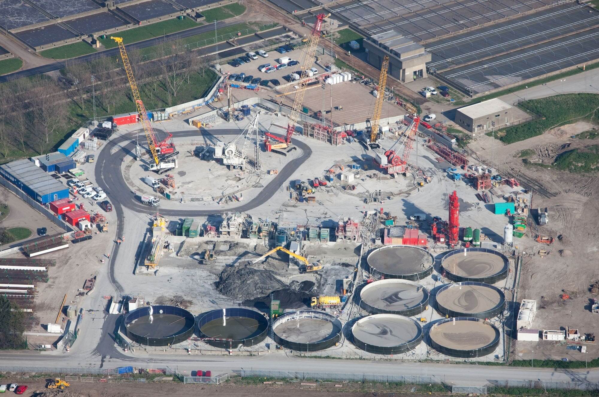
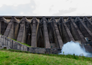
The Thames Tideway Tunnels programme is a key component of the upgrade of London’s combined sewer system. The first section to be constructed is the Lee Tunnel between the Beckton Sewage Treatment Works and the Abbey Mills Pumping Station.
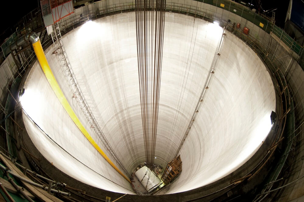
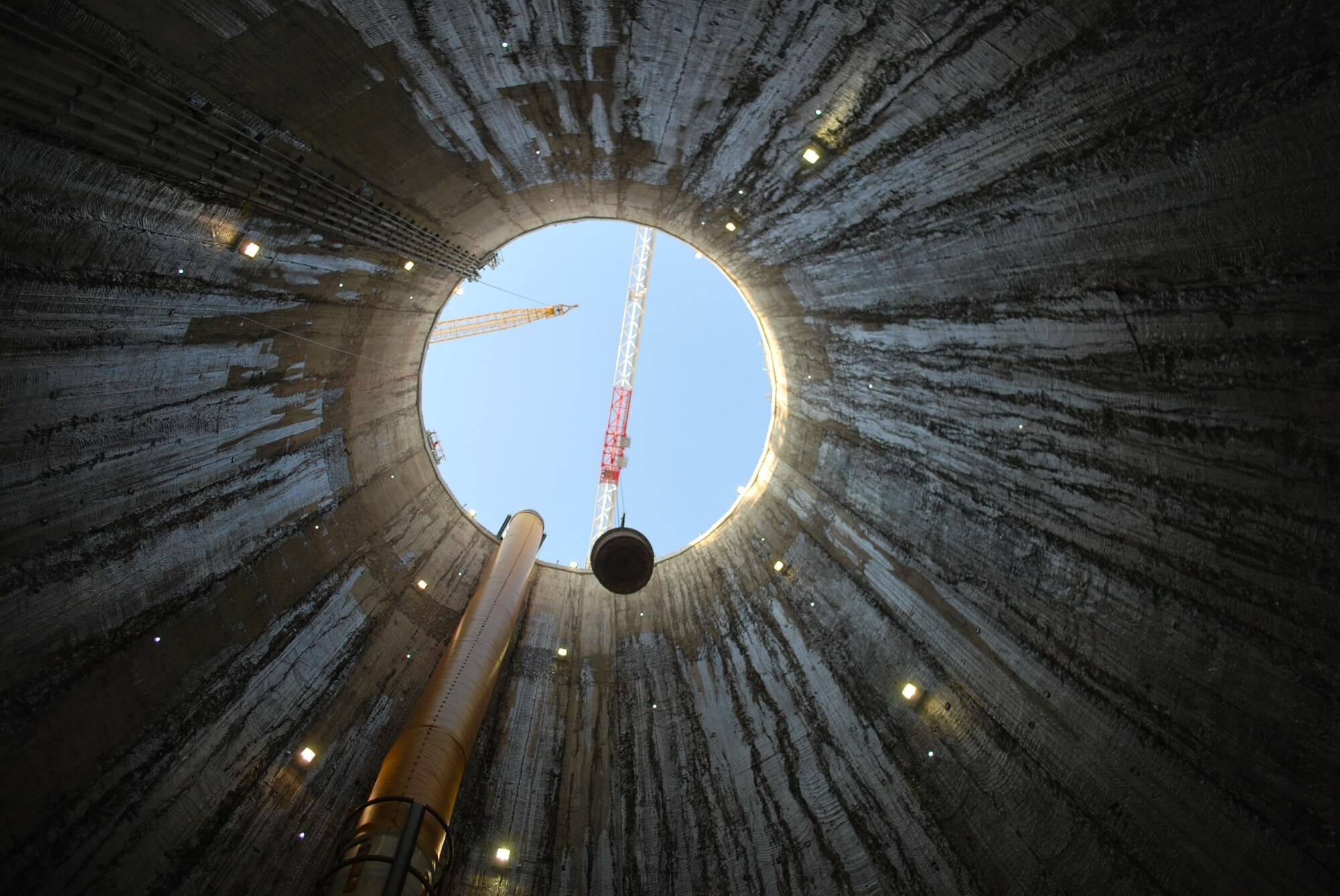
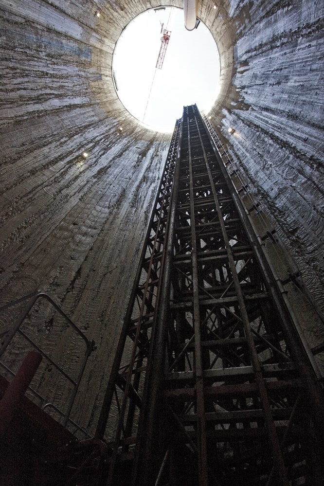
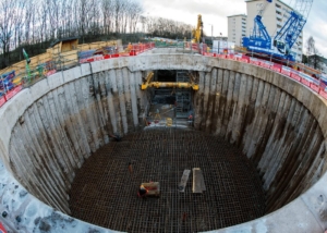
This comprised the construction of five shafts and a 7.2m internal diameter tunnel running 6.9km from Abbey Mills to Beckton. The shafts are some of the largest ever constructed in Europe and range from 20 to 38m finished internal diameter with diaphragm wall depths from 84 to 98m. Each shaft is formed from a reinforced concrete diaphragm wall with a secondary fibre-reinforced concrete lining and conventionally reinforced concrete base slab.
MVB, a joint venture of Morgan Sindall, VINCI Construction Grands Projets & Bachy Soletanche delivered the Lee Tunnel project for Thames Water. They worked with Thames Water and their Project Management Team in a collaborative manner under an NEC contract with Mott MacDonald and Morgan Sindall Underground Professional Services as designers.
GEOLOGY
The stratigraphy was similar to that encountered under much of east London, comprising a sequence of superficial deposits overlying Tertiary clays, sands and chalk. The chalk (weak limestone of 3 to 6 MPa) was encountered over approximately 50% of each shaft towards the base and was of grade A. The degree of fracturing was variable, but greater near the Thanet Sand interface. Bands and nodules of extremely strong flint were encountered.
DIAPHRAGM WALL DESIGN
The design followed EC2 & EC7 and had to consider an assessment of chalk stiffness, high hoop stresses, large multiple openings and non-axisymmetric loadings. A subgrade reaction programme “Paroi 2”, developed by Bachy Soletanche, was used for the design. Plaxis version 9 was also used to undertake axisymmetric finite element calculations and a Mohr Coulomb soil model without strain hardening used.
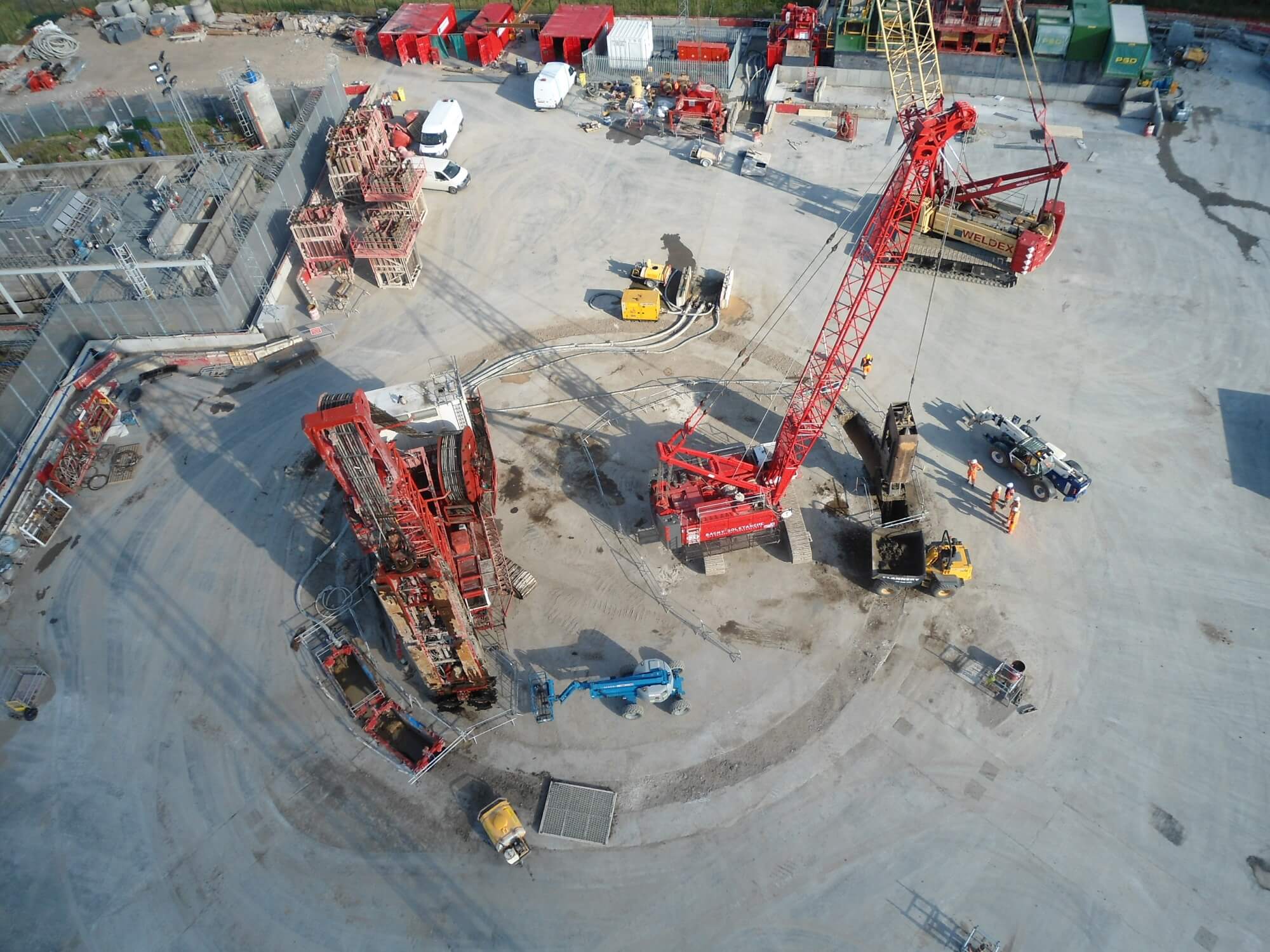
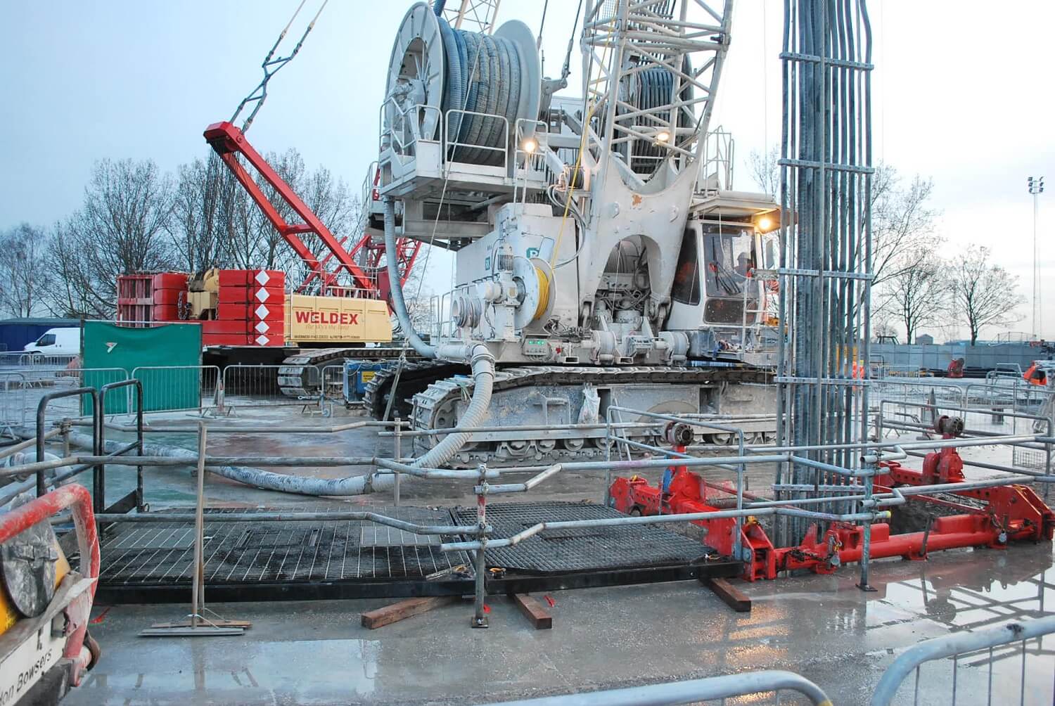
All the diaphragm wall panels were excavated using the Hydrofraise unit (reverse circulation milling machine) as a series of overlapping rectangular panels forming a faceted circle. Primary panels were up to 7.2m wide comprising 3 “bites”. Secondary single bite panels overlapped and cut into the concrete of the primaries. Instrumentation informed the operator of the plan position, inclination and twist of the cutter body during excavation.
Hydraulic rams and pressure plates were fitted to the cutter bodies and jacked against the side of the panels to change the inclination/orientation of the cutter to achieve the required tolerances. A Koden ultrasonic echo sensor device was also used to survey the position of the panel once complete. Results were electronically transferred into 3D CAD producing an as-built of the excavation. This acted as a calibration of the onboard instrumentation and provided confidence in its accuracy.
The 3D surveys provided confidence to the excavation team that there would not be any excess inflows of soil and water and the verticality observed achieved and in many cases exceeded the specification of 1 in 300 for all panels.
CAGE DESIGN AND REPLACEMENT
Each diaphragm wall panel contained reinforcement over its full depth. In the primary panels three separate cages were placed and, since 22.5m was the maximum cage length which could be transported to site, a three-bite primary panel required 15 separate pieces of reinforcing cage to be installed. Cages were connected using threaded couplers. The cages underwent temporary works design checks for safe handling, lifting, splicing and placing. The shape of the overlap between the panels was trapezoidal. To even up the shape of the overcuts, polystyrene panels were connected to the outside of the primary panel cages and the cages were spaced apart using steel leaf springs so that the polystyrene was removed during the excavation of the secondary panels.
Concrete was supplied from an onsite batching plant. Placement rates for concrete pours up to 1300m3 varied from 35 to 100 m3/hr depending on panel size and location. The high strength concrete required a complex mix design in order that the required workability was maintained throughout.